Layout & Structure Design of PLC Control Cabinet
The PLC control cabinet refers to the programmable control cabinet, and the control cabinet refers to a complete set of control cabinets, which can realize the control of motors and switches. The PLC control cabinet has protection functions such as overload, short circuit and phase loss protection.
PLC control cabinet can complete equipment automation and process automation control, realize perfect network function, stable performance, scalability, strong anti-interference and other characteristics, is the core and soul of modern industry. PLC control cabinets, frequency conversion cabinets, etc. can be tailored according to user needs to meet user requirements, and can be matched with human-machine interface touch screen to achieve the purpose of easy operation. The equipment can also communicate with the DCS bus host computer modbus, profibus and other communication protocols for data transmission; industrial computer, Ethernet, etc. to achieve control and monitoring.
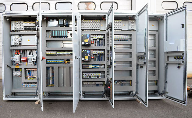
PLC control cabinet structure
Air switch
A general air switch, this is the power control of the entire cabinet. Believe that every cabinet must have something.
PLC
This should be selected according to the project needs. For example, if the project is small, it can be an integrated PLC directly, but if the project is relatively large, it may require modules and card-type, and may also require redundancy (that is, two sets are used alternately).
Power Supply
A 24VDC switching power supply. Most PLCs have their own 24VDC power supply. Whether this switching power supply is needed depends on whether it is really needed.
Relay
Generally, the PLC can directly send the command to the control loop, but it may also be relayed by the relay first. For example, if the output port of your PLC is powered at 24VDC, but the diagram drawn in your control loop requires the node supplied by the PLC to be 220VAC, then you must add a relay to the PLC output port, that is, the command is issued. When the relay operates, the node of the control loop is then connected to the normally open or normally closed point of the relay. It is also according to the situation to choose whether to use the relay.
Terminals
This is definitely an essential thing for every cabinet. It can be configured according to the number of signals. If it is just a simple PLC control cabinet, these things are basically needed. If you need other things in your control cabinet, it depends on the situation. For example, you may need to supply power to some on-site instruments or small control boxes, and you may have to increase the number of air switches. Or if you want to connect the PLC to the host computer, you may need to add a switch or something. Subject to availability.
Conditions of use of PLC control cabinet
Power supply: DC 24V, single-phase AC 220v, (-10%, +15%), 50HZ
Protection class: IP41 or IP20
Environmental conditions: The ambient temperature is between 0°C and 55°C to prevent direct sunlight; the relative humidity of the air should be less than 85% (no condensation). Keep away from strong vibration sources and prevent frequent or continuous vibration with a vibration frequency of 10-55HZ. Avoid corrosive and flammable gases.
PLC electrical control cabinet wiring
For the normal operation of a system production line, the electrical plc and slave stations are equivalent to the human heart and blood vessels, and no one can do without the other, but if the heart is to operate normally and the blood vessels flow normally, then we must start from the basics—wiring .
The wiring is connected to the PLC-cpu template, and the front connector terminal must be pressed against the nose. You can use 0.75 square and 1 square. If the wiring is connected to the front connecting line, the pressure line is loose or the virtual connection will affect the stability of the entire system.
The power supply is divided into 220V and 24V. The signal line is divided into digital input and output. The signal line and the power line should be pressed against the nose in the terminal, and the fixing screw should be used to lock it, and pull it by hand to see if it is firm.
The following is an example of a site: the site is a small reversing rolling mill. Before commissioning, the signal lines and power supplies from the transmission cabinet to the PLC cabinet and other slave stations are calibrated one by one, but there is no calibration of the template line in the console to the relay and the power supply. The signal line of the terminal, normally, before the cabinet is sent from the factory to the site, there is a factory debugging record. This line has been debugged with electricity, and there should be no problem. The knob switch and tension of the console are sometimes good and sometimes bad. After the on-site parking, check the DP network and DP communication plug. There is no problem, and the knob of the console is also normal. After observing that the template light does not light up when the knob switch is turned on, the input signal light is not on. Check the wiring of the connector in front of the template, and pull it by hand, but more than one is loose. Nearly 8 wires in the first row are loose. No wonder it will report a fault. After re-tightening, start the car to roll the steel and return to normal.
Please feel free to ask for any inquires for your needs, we will submit our best price for all the original brand new items!
Do not hesitate, drop you messages and we will get back to you in any minute!
E-mail : sales1@amikon.cn
Mobile/WhatsApp/Skype: +86 18020714921
|
3RP1505-1AP30
|
6ES7331-7SF00-0AB0
|
6ES7323-1BH01-0AA0
|
|
6EP1434-2BA00
|
6ES7331-7RD00-0AB0
|
6ES7212-1BB23-0XB8
|
|
6EP1434-2BA00
|
6ES7972-0BA12-0XA0
|
6ES7151-1AA05-0AB0
|
|
6EP1336-2BA00
|
PC-GF 20/720-2001-01
|
6ES7331-7NF00-0AB0
|
|
6DD1681-0GK0
|
6ES7223-1PH22-0XA0
|
6ES7214-1BD23-0XB0
|
|
6ES7972-0BA41-0XA0
|
6ES7216-2AD22-0XB0
|
6ES7214-1BD23-0XB8
|
|
6ES7315-1AF00-0AB0
|
6ES7322-1HH01-0AA0
|
6ES7332-5RD00-0AB0
|
|
6ES7340-1CH02-0AE0
|
6ES7222-1HF21-0XA0
|
6ES7315-2AG10-0AB0
|
|
6ES7321-1BH02-0AA0
|
6ES7222-1HF22-0XA8
|
6ES7315-2AG10-0AB0
|
|
6ES7321-1BH01-0AA0
|
6ES7357-4AH01-0AE0
|
6ES7314-1AF11-0AB0
|